First Angle and Third Angle are two methods orthographic projection used in technical drawing and normally comprises the three views (perspectives): front, top and side. Usually front, top and side views are drawn so that a person looking at the drawing can see all the important sides.
Orthographic drawings are useful especially when a design has been developed to a stage whereby it is almost ready to manufacture. First angle and third angle only differ in the position of the top, front and side views.
What is First Angle Projection?
First angle projection is a method in engineering drawing and technical documentation of representing three-dimensional objects in two dimensions. It is a standardized system for creating orthographic projections (drawings that show an object from multiple views, the front, top, and side views.
In first angle projection, the object is placed in the first quadrant of the projection planes, with the primary views projected onto the planes in such a way that the planes are between the observer and the object. The observer’s position is considered to be inside the object, looking towards the planes. This means that the front view is projected onto the plane closest to the object, and the top view is projected onto the plane above it. The right-side view is then projected onto the plane to the right of the front view, and so on.
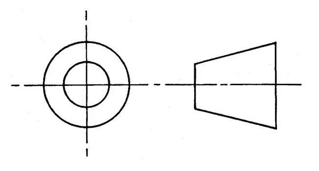
First angle projection Symbol

The main views in first angle projection are:
- Front View (Elevation): This view represents the front face of the object as seen from the observer’s perspective (height and width dimensions of the object).
- Top View (Plan View): This view represents the top face of the object (length and width dimensions).
- Right-Side View (Profile View): This view shows the right side of the object (The length and height dimensions).
First angle projection method is used in Europe, India, Canada and the rest of world as a default projection system. It is defined by international standards, such as ISO 5456 and DIN 6, which specify the rules and conventions for technical drawings.
What Is Third Angle Projection?
Third angle projection is a method of creating a two dimension drawing of a three dimension object. Third angle system is used commonly in North America as a default projection system for industrial designs or for product fabrication. It is alternatively described by others as American projection.
In third angle projection, the object is placed in the third quadrant of the projection planes. This means that the object is placed below and behind the planes, and the observer’s position is considered to be outside the object, looking towards the planes. The views are projected onto the planes as if they were transparent, and the planes are unfolded to display the various views of the object.
The main views in third angle projection are the same as in first angle projection. Front View (Elevation),Top View (Plan View) and Right-Side View (Profile View). However, The arrangement of the views is different in third angle projection compared to first angle projection.
- The front view is projected onto the plane furthest away from the object i.e the bottom plane.
- The top view is projected onto the plane above the front view.
- The right-side view is projected onto the plane to the right of the front view.
Third Angle Projection Symbol

In very many countries and according to ISO Standards state that these two systems of projection (1st & 3rd) are equally acceptable but they should never be mixed on the same drawing. The projection symbol must be added to the completed drawing to indicate which system has been used.

Also Read: Difference Between Parallel And Perspective Projection
First Angle Vs Third Angle Projection In Tabular Form
| BASIS OF COMPARISON | FIRST ANGLE | THIRD ANGLE |
| Observer’s position | First angle projection: The observer is considered to be inside the object, looking towards the projection planes. | The observer is considered to be outside the object, looking towards the object and projection planes. |
| Object placement | The object is placed in the first quadrant of the projection planes. | The object is placed in the third quadrant of the projection planes. |
| Arrangement of views | The front view is projected onto the plane closest to the object, and subsequent views are placed on planes behind it. | The front view is projected onto the plane furthest away from the object, and subsequent views are placed on planes in front of it. |
| Primary views | Front view, top view, and right-side view are the primary views. | Front view, top view, and right-side view are also the primary views |
| Projection | The right-side view is projected to the left of the front view and the top view is projected onto the bottom of the front view | The right view is projected onto the right side of the front view and the top view is projected above the front view. |
| Orientation of views | The views are oriented in a clockwise direction around the object. | The views are oriented in a counterclockwise direction around the object. |
| Symbol notation | The symbol “1” is used to denote first angle projection on engineering drawings. | The symbol “3” is used to denote third angle projection on engineering drawings. |
| Application | Commonly used in Europe, Asia, and other parts of the world. | Predominantly used in North America and Australia. |
| Industry standards | Adheres to standards such as ISO 5456 and DIN 6. | Adheres to standards such as ASME Y14.3 and CSA B78. |
Key Takeaways
What You Need To Know About First Angle Projection
- The object is placed in the first quadrant for the first angle projection.
- To get the first angle projection, the object is placed between the plane of projection and the observer.
- In the first angle projection schema, the plane of projection is assumed to be opaque or non-transparent. The object is placed in front of the planes and each view is pushed through the object which places the vertical plane behind the object and pushes the horizontal plane underneath.
- In the first angle projection, the orthographic view is projected on a plane located beyond the object and the observer is on the left side of the object and projects the side view on a plane beyond the object.
- The right side view is projected to the left of the front view and the top view is projected onto the bottom of the front view.
- First angle projection method is used in Europe, India, Canada and the rest of world as a default projection system.
What You Need To Know About Third Angle Projection
- The object is placed in the third quadrant for the third angle projection.
- To get a third angle projection, the plane of projection is between the observer and the object.
- In the third angle projection, the plane of projection is assumed to be transparent and the object is placed below the horizontal plane and behind the vertical plane.
- In third angle projection, the observer is on the right side of the object and the orthographic view is projected on a plane located between the view point and the object.
- The right view is projected onto the right side of the front view and the top view is projected above the front view.
- Third angle projection is used in Australia and United States as a default projection system for industrial designs for product fabrication.
Similarities Between First Angle And Third Angle Projection
- Both are graphical methods used in engineering drawings.
- Both are schemas used for multiview projection of three-dimensional objects using a series of two-dimensional drawings.
- Both methods of orthographic projection result in the same six principal views of the object except the arrangement of views and the state of plane of projection.
- Both are used to obtain engineering drawings for clarity.
Also Read: Difference Between Orthogonal And Oblique Projection