Encoder In Digital Logic
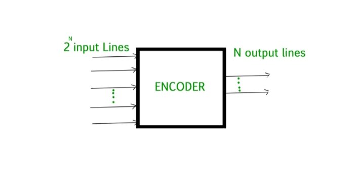
An Encoder is a combinational circuit that performs the reverse operation of Decoder. It has maximum of 2n input lines and ‘n’ output lines, hence it encodes the information from 2n inputs into an n-bit code. It will produce a binary code equivalent to the input, which is active high. Therefore, the encoder encodes 2n input lines with ‘n’ bits. For simple encoders, it is assumed that only one input line is active at a time.
Facts About Encoder
- The encoder is basically a combinational circuit that converts the applied information signal into a coded digital bit stream.
- The applied signal is the active signal input.
- The number of inputs accepted by an encoder is 2n.
- The output lines for an encoder are n.
- The operation of an encoder is quite simple.
- In a communication system, the encoder circuit is installed at the transmitting end.
- OR gate is the basic logic element used in the encoder.
- It is used in E-mail, video encoders etc.
Decoder In Digital Logic
The combinational circuit that changes the binary information into 2n output lines is referred to as Decoder. The binary information is passed in the form of ‘n’ input lines. The output lines define the 2n –bit code for the binary information. In simple words, a decoder is a circuit that changes a code into a set of signals. It is referred to as decoder because it does the reverse of encoding (recovering the original information signal from the coded bits). At a time, only one input line is activated for simplicity. The produced 2n-bit output code is equivalent to the binary information.
Facts About Decoder
- A decoder is a circuit that changes a code into a set of signals. It is referred to as decoder because it does the reverse of encoding (recovering the original information signal from the coded bits).
- Decoder accepts coded binary data as its input.
- The number of input accepted by decoder is only n inputs.
- The output lines of a decoder are 2n.
- The operation of an encoder is quite simple but the operation of the decoder is complex as it requires understanding the coding format of the encoder.
- In a communication system, the decoder circuit is installed at the receiving side.
- AND gate along with NOT gate is the basic logic element used in the decoder.
- It is used in microprocessors, memory chips etc.
Also Read: Difference Between Combinational And Sequential Logic Circuits
Difference Between Encoder And Decoder In Tabular Form
| BASIS OF COMPARISON | ENCODER | DECODER |
| Description | The encoder is basically a combinational circuit that converts the applied information signal into a coded digital bit stream. | A decoder is a circuit that changes a code into a set of signals. It is referred to as decoder because it does the reverse of encoding (recovering the original information signal from the coded bits). |
| Input Signal | The applied signal is the active signal input. | Decoder accepts coded binary data as its input. |
| Number Of Input | The number of inputs accepted by an encoder is 2n. | The number of input accepted by decoder is only n inputs. |
| Output lines | The output lines for an encoder are n. | The output lines of a decoder are 2n. |
| Operation | The operation of an encoder is quite simple. | The operation of an encoder is quite simple but the operation of the decoder is complex as it requires understanding the coding format of the encoder. |
| Installation | In a communication system, the encoder circuit is installed at the transmitting end. | In a communication system, the decoder circuit is installed at the receiving side. |
| Logic Element | OR gate is the basic logic element used in the encoder. | AND gate along with NOT gate is the basic logic element used in the decoder. |
| Application | It is used in E-mail, video encoders etc. | It is used in microprocessors, memory chips etc. |
Also Read: Difference Between Negative And Positive Feedback

